EPR-203 Satellite Positioner and EPS-103 Controller
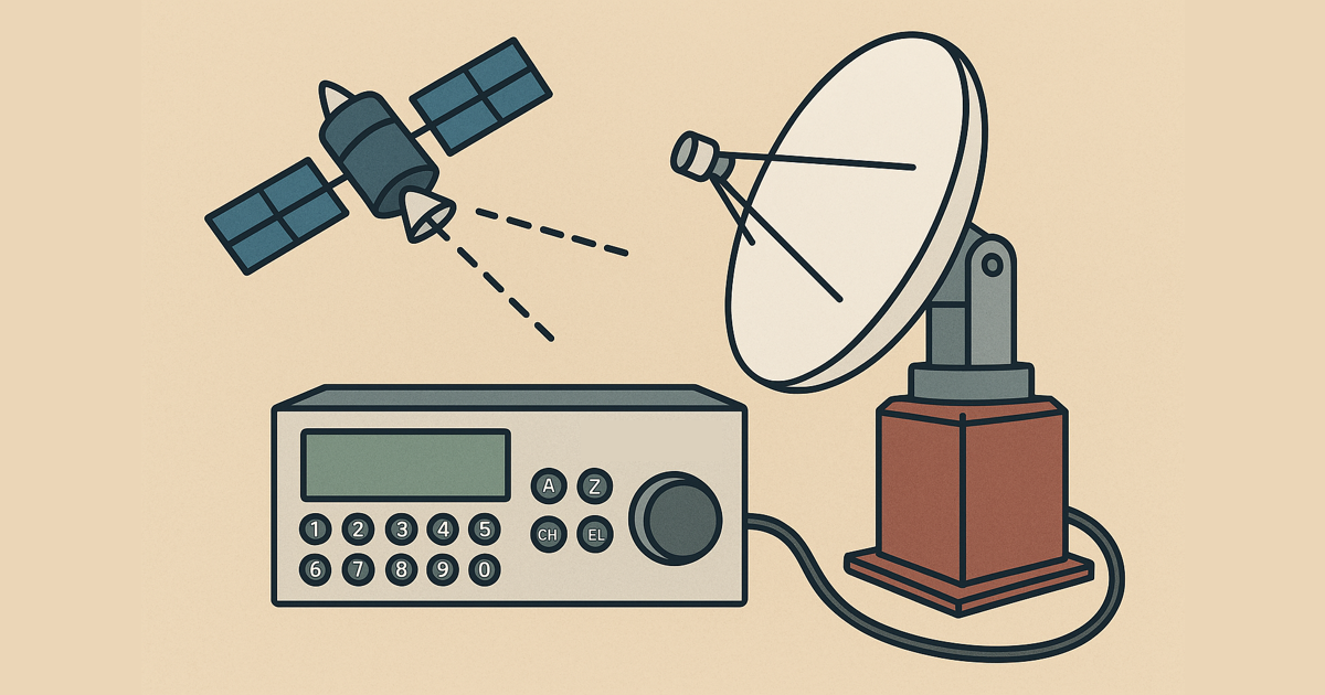
The EPR-203 is an antenna rotor that was marketed in the 1980s by the Japanese company Nagano Japan Radio (NJR). It includes the EPS-103 controller unit (also known as the NITEC Satellite Selector EPS-103) used to control the rotor. This system was developed at the time for satellite reception and enables precise alignment of an antenna in both horizontal (azimuth) and vertical (elevation) axes. In amateur radio, the EPR-203/EPS-103 combo is particularly suited for satellite communication and even EME (Earth-Moon-Earth).
The EPS-103 controller was originally designed as a stand-alone solution. It features its own control panel with keypad and display for manual operation and to recall preprogrammed satellite positions. Later on, an add-on board was developed that allowed control via an RS232 interface.
A few years ago, I got the EPR rotor and EPS-103 controller from Norbert, a fellow amateur radio operator from our local club (E15). The EPS-103 came with a first-generation add-on board.
 The add-on board inside my EPS-103
To make the EPS controller useful for amateur radio applications, I needed to figure out how to control it automatically. As you can see in the picture, a DSub9 socket was seemingly intended. I hoped that it was in fact an RS232 interface. Two questions I got in my mind:
- Does the existing firmware support RS232?
- How is RS232 processed by the board?
So I tried to find schematics for the board - or at least a photo showing the DSub9 and the IC. I couldn’t find a schematic, but I did find a picture of a newer version of the add-on board clearly showing the RS232 socket and the IC.

This confirmed that it really is RS232, and that the IC used is a TC232. On my board, it’s installed as a SOC (System-on-Chip), but the pinout matches the DIP version. Unfortunately, this specific IC is no longer manufactured, and the SOC version currently costs over 40€ on eBay. Fortunately, there are cheaper alternatives. The MAX232 by MAXIM costs about 3€ on eBay, has the same pinout, but differs in VCC voltage and capacitor requirements. Luckily, the EPS controller supplies exactly the voltage the MAX needed.

Since I didn’t want to modify the housing of the EPS controller, I routed the DSub9 socket out of the case using a flat ribbon cable.
Connecting the controller to the computer would now answer the question of whether the firmware supports RS232. And it does. 🥳 Unfortunately, no documentation exists for this firmware version. EGIS (the German supplier) only has documentation for the latest version, which doesn’t appear to be compatible with my board. Still, the commands for positioning and querying the current position remain unchanged.
To set the position:
1
2
AZ=OOO.OO   # Goto azimuth angle 000.00 (O.01 bis 360°)
EL=OOO.OO   # Goto elevation angle 000.00 (O.01 bis 90°)
To read the current position:
1
2
AZ=?
EL=?
The next step is to write a driver or interface to connect the controller with GPredict.
I’ll document the next steps in future posts.